Social:
Controlling Multiple I2C Devices with Arduino
By Netopya on Sun Jun 22nd 2014 5:15 PM
A project I was working on a while ago encountered a problem when we decided to use multiple I2C color sensors. The I2C protocol relies on the fact that each device you connect as a unique address. But in the case of the sensors we were using, the address is hard wired into the device, so connecting multiple identical sensors with the same permanent address would creating a conflict. This problem was easily solved with the use of an I2C multiplexer. Not much information was available on the web regarding this solution, but after doing some research we learned that the implementation is very easy. Read on pass the break to see what we learned and how you can use multiple identical I2C devices in your Arduino projects.
Full Gallery:
Introduction
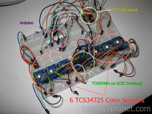
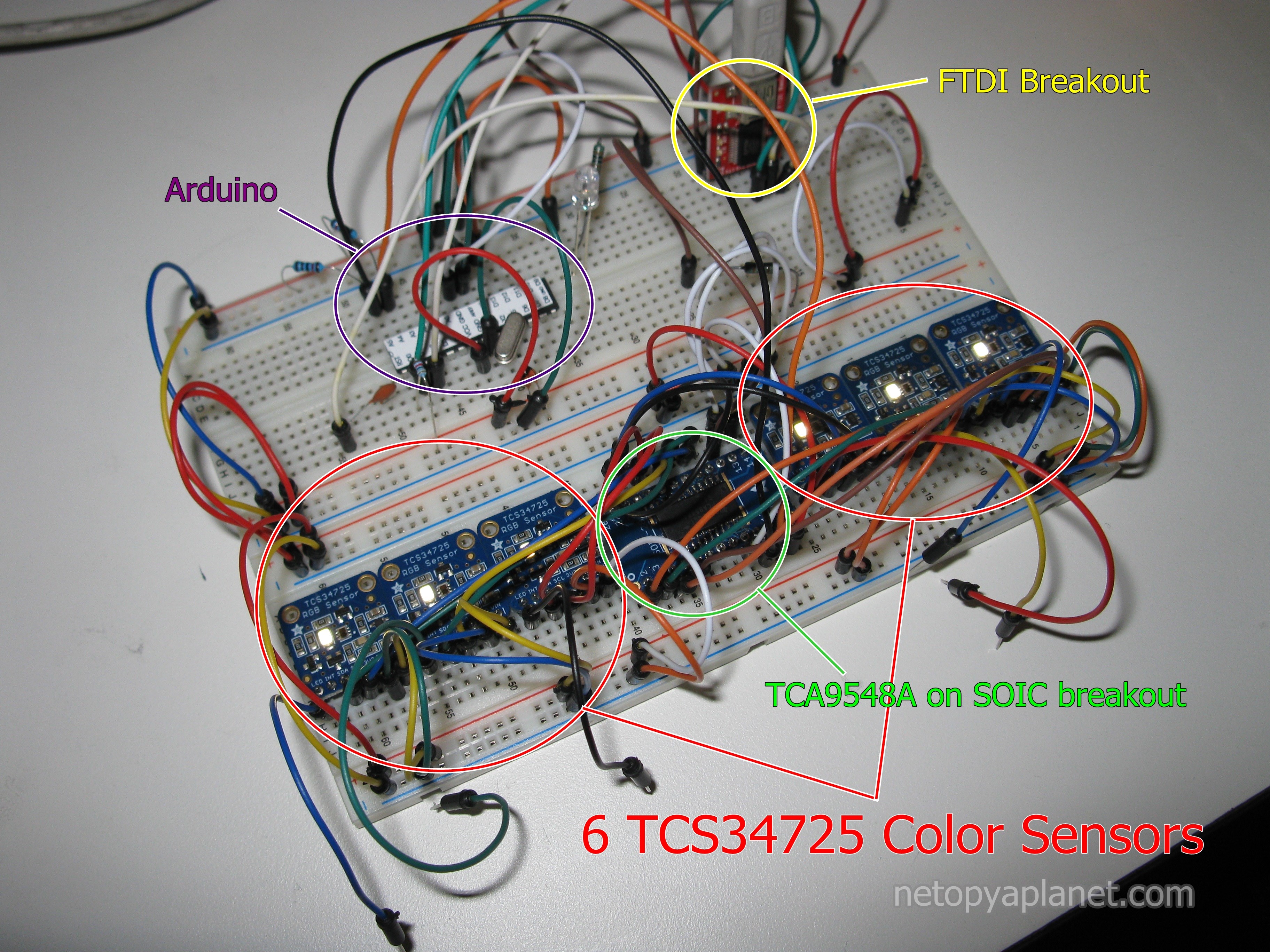
In our project, we used six Adafruit I2C color sensors to sort up to six ping pong balls simultaneously. As we already discussed, this is problematic since each sensor is identical with the same address. An I2C multiplexer can be used to solve this issue but only allowing one color sensor to be accessed at a time. The multiplexer we chose was the Texas Intruments TCA9548A, which can switch up to 8 I2C lines. The two I2C lines of each color sensor (SDA and SCL) were connected to unique outputs on the I2C multiplexer. The multiplexer has its own address that could be written to by the Arduino with the Wire library to connect (and disconnect) the individual I2C lines of each sensor. The rest of this tutorial will explain the proof of concept that we realized to test this setup.
Components and Wiring
- 6x Adafruit Color Sensor (#1334)
- I2C multiplexer TCA9548A
- Adafruit SOIC breakout (#1208)
- Breadboard/Breadboard wires
- Arduino
Wiring
The only complication with the wiring of this project is the TCA9548A chip itself, which commonly comes in a SOIC (surface mount) package, which is difficult to solder by hand and cannot be placed on a breadboard. In our case we used the Adafruit PCB SOIC-28 breakout board so that we could place the chip on and breadboard, and later insert into female headers on a custom PCB. Note that the breakout has 28 pins while the chip only has 24 pins; the extra 4 pins just remained unused (Consider that this messes up the numbering scheme printed on the breakout). On the wiring diagram above, I used a proper SOIC-24 breakout so that there is no funny numbering scheme (These are just harder to find). Soldering the surface mount chip was quite painstaking but we patiently succeed on our first try.
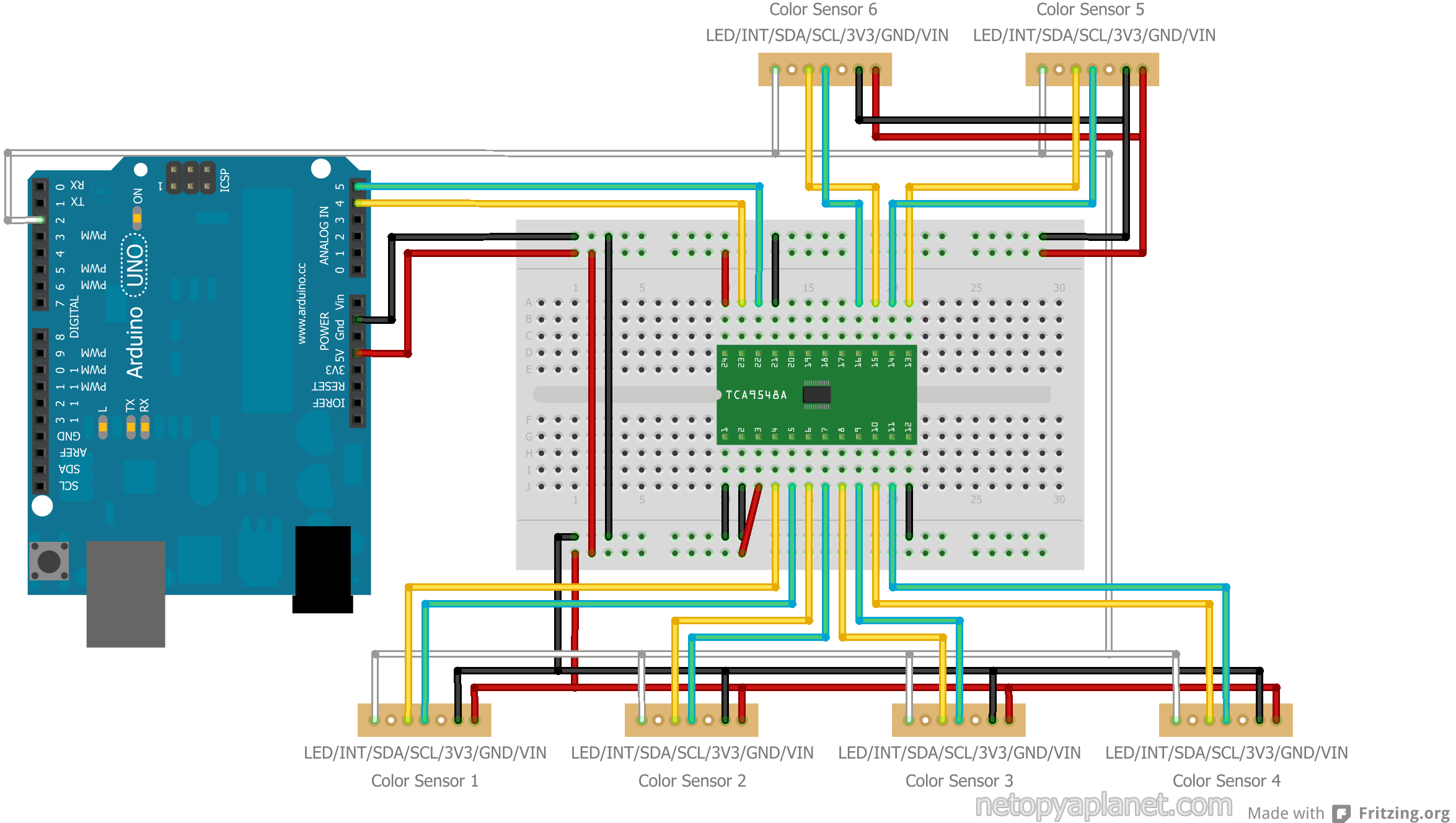
The rest of the wiring of this project is quite straight forward. The SCL and SDA inputs of the TCA9548A (pins 22 & 23) should be connected to the I2C pins of the Arduino (analog pins A5 and A4) with some pull-up resistors. Each of the SCL and SDA lines of the color sensors should be connected to their own SCL, SDA output on the TCA9548A.
Programming
To program the test bench, I based my code on the Adafruit example project for the sensors, but made modifications for our setup. The two fundamental differences were that I changed the color sensor object into an array of color sensor objects (six of them) and I inserted the following code to switch the I2C multiplexer to the sensor I wished to communicate with before any code that communicated with the sensors.
	Wire.beginTransmission(0x70);
    Wire.write(1 << i);
    Wire.endTransmission();
This code simply begins the communication using the Wire library to the address of the I2C multiplexer (0x70) as stated in the documentation. Then it writes a number representing the number of the color sensor we wish to access. For example if we wanted to access the third sensor (the sensor connected to SDA2 and SCL2), we would assign a value of 2 to the i variable. Finally the Wire library function that completes the transmission is called. To further understand necessity the bit shift operator, the data sheet tells us that it reads the values of each bit in a 8-bit word to determine the state of each output. This is quite powerful and would allow various sensors to be selected and connected simultaneously, but in our case we only want one line to be activated at a time.
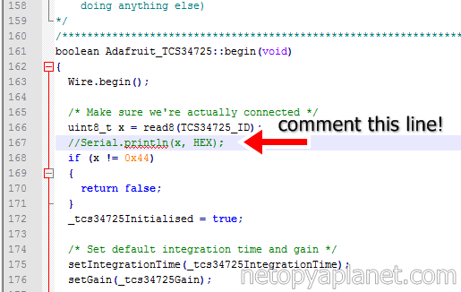
To retrieve the data from the sensors basing of the Adafruit example, I put all of the sensing code into a for loop iterating over the six sensors, making sure to use the Wire functions to switch the I2C multiplexer to the appropriate line. I modified the serial communication code by using ":" delimiters for each RGB and clear values, and ";" delimiters to separate color sensors. I removed the gamma table code because we were not concerned about the color accuracy of the sensor, just if it would be able to distinguish between white and orange. Another final change is that the Adafruit library for the color sensor announces over serial that it is connected when you initialize the sensor, which interferes with our serial communication. So solve this, simply comment out the line in the library with the problematic code. In the Adafruit_TCS34725.cpp file, just note line 167.
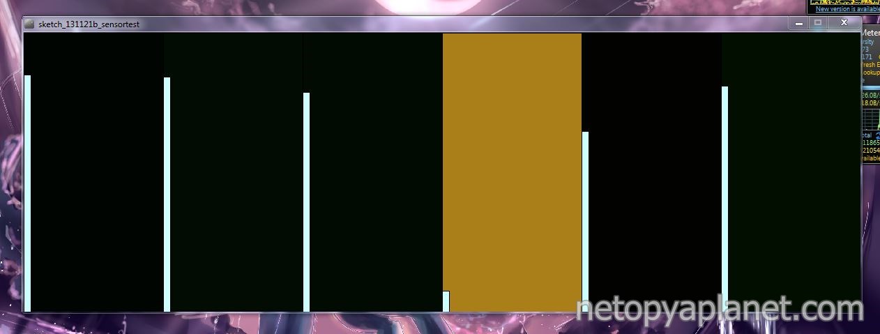
To display this information on your computer I use a Processing app that reads the serial information and displays on the screen. There are six boxes showing the color from the sensor along with a vertical bar which indicates the clear value.
Conclusion
This project was one component that was used on robot for a competition I participated in called the Engineering Games. This part of the robot was used to quickly sort the ping pong balls required for the challenge. A video showcasing our team and our robot for the competition can be see below. Note at timestamp 1:23 where the sorting mechanism is shown in action.
In conclusion, I hope that sharing this project with you helped you to learn how to use multiple color sensors with an Arduino. Even if multiple I2C sensors have the address, it is very simple to wire them together though an I2C multiplexer and communicate to the multiplexer with 3 lines of code. If you have any questions, feel free to email me. As always, code is below. Enjoy!
Github repo
Arduino code
Processing code
Color Sensor code library (Adafruit)
Comments
gabriel on Mon Jul 6th 11:45 AM said:
hello, I'm a beginner on i2c and I have just been having a hard time finding examples that show multiple slaves by just using the I2C library or some other code modification. It just seems overkill, yet practical, to use an extra part when the protocol provides for this already. Do you have any suggestions?
Netopya on Mon Aug 31st 1:57 PM said:
@gabriel - Hi, the multiplexer is only required when multiple devices with the same address are on the I2C line (which is usually the case when using multiples of the exact same type of device). If this is not the case (all devices have unique I2C addresses) then you can simply connect the devices in parallel with all the SDA lines connected together and all the SCL lines connected together. Finally you would just need to include some pull-up resistors (about 10K) between the lines and the voltage source.
Ara Keshishian on Fri Jan 1st 9:42 PM said:
Hello- great information- I am not able to follow the tca9458A pin numbers to the board that I have. For example only my board purchased for the arufuirt I am assuming pin 1 is VIN and 2 is GND. However then the pin 22 and 23 do not correspond to the described pins above. any help is appreciated.\r\nthank you
Netopya on Tue Jan 5th 12:24 PM said:
@Ara Keshishian - Hi, you're going to need to follow the documentation for the specific model of chip you have. There can be significant differences between chips, especially if they are from different manufacturers. On the TCA9548A, GND is 12 while VCC is 24. Other pins are connected to ground or power in order to setup various features of the chip (for example the address pins are grounded). If differences are accounted for, you should have no difficulty obtaining identical functionality.
samNZfoil on Tue Jul 19th 2:57 PM said:
Hi there,\r\n\r\nIm working on a similar project using the TCA9548A mux and 4 BNO055 orientation sensors. i think i have my code correct now and can get 2 BNO\\\'s working perfectly but when I add a 3rd a problem occurs in the setup loop when the 3rd BNO fails to start up? I see that you use pull up resistors in your circuit but i can\\\'t really follow the wires to understand which pins they are between? is it pin 4 & 5 of Arduino and SDA/SCL pins of the mux? can you explain the function of the pull up resistors?\r\n\r\nregards\r\nSam
Netopya on Sun Aug 21st 9:50 AM said:
@samNZfoil - Hi, I've had similar issues where some sensors would fail to be detected by the Arduino. I believe these problems were caused by faulty wiring since re-doing the wiring fixed the issues. I failed to indicate the location of the pull up resistors in my diagram but you are correct in their placement along the lines connected to pins 4 & 5 of the Arduino. They serve the purpose of helping to provide a clean I2C signal by "pulling up" the voltage when the Arduino isn't actively pulling it down.
samNZfoil on Mon Aug 29th 2:29 PM said:
Hi Neyopya thanks for the info. I found a solution to my problem without using any pull up resistors but when calling the bno.begin() function in the setup loop i found i needed to call it twice for the arduino to confirm that the sensors had actually started. eg. bno.begin(); if (!bno.begin()) { while(1) }
dhiyena on Mon Jan 16th 8:26 PM said:
Hi! I am a newbie on I2C >.< Can you explain why we must use I2C Multiplexer (eg. TCA9548A) if we want to use many sensors with the same address? Can we just use a 16-channel analog multiplexer (eg. HEF4067BP)? If we can\\\'t a 16-channel analog multiplexer, please give me a reason. Thank you
Netopya on Wed Feb 8th 7:17 PM said:
@dhiyena - I don't know enough about I2C to know if a regular 16-channel multiplexer would work, but I would that assume it would work! The main advantage with the TCA9548A for us is that since it ran off the I2C bus it didn't use up any of our precious Arduino pins!